MRI Iinstrumentation
- Overview
- In the flesh...
- Some very big magnets..
- ..and some slightly smaller ones
- The RF part
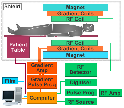
The diagram shows a cross-sectional view of a typical MRI scanner.
The key elements are the magnet, gradient coils and RF system.
The operator selects the pulse sequences needed for a particular clinical application from a menu or icons on the computer screen, and the computer then generates the pulse sequence via the gradient and RF hardware.
Source: Philips
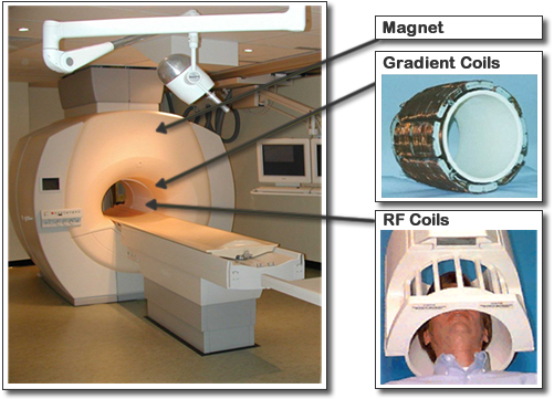
The magnet is the most obvious component of the MR system.
- Most modern systems are based around a superconducting magnet with field strength in the range 1.5-3.0 T (tesla). By way of comparison, the earth’s magnetic field has an average strength of about 0.00005 T.
- A superconductor is a material which, if cooled below a certain temperature, conducts electricity without resistance and therefore without heating.
- It would not be possible to generate such high magnetic fields using conventional electromagnets, because it would not be possible to dissipate the heat produced by the large currents needed.
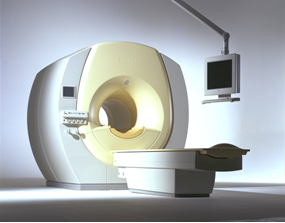
- In order to keep the magnet cold enough to remain superconducting, it is emerged in a huge doughnut-shapes Dewat flask filled with liquid helium. This is hidden behind the fibre glass covers of the scanner.
Source: Siemans
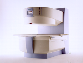
- Scanners are also available that use resistive or permanent magnets.
- These have much lower fields, of the order 0.2-0.3 T, and therefore lower image quality.
- However, they can be built to much more open designs, which has advantages in applications such as interverntional MRI and for imaging obese and paediatric patients.
- Recently, open superconducting scanners have been developed, and this is likely to be an important trend in the future.
- The overall performance of the scanner depends on the performance of the gradient and RF systems and also the host computer system (particularly its speed) as well as the magnet.

Source: Philips

L-R: head coil (birdcage design) and knee coil
Source: Philips

L-R: body, cardiac and breast phased array coils
Source: Philips
RF coils are available in a range of designs
- The simplest are known as surface coils because they are simply placed on the surface of the patient’s body.
- Surface coils have high sensitivity locally, but signal falls away rapidly with distance from the coil. They are therefore useful for imaging superficial areas such as the orbit or the shoulder, but not for example the brain.
Selection of surface coils
- Volume coils enclose the body part being imaged and so achieve uniform signal intensity throughout the imaged volume.
- The modern trend is towards phased array coils, essentially a set of surface coils connected together to provide volume coverage.
- The signals from the different coil elements are combined using sophisticated mathematical algorithms in order to produce a uniform image
- These arrays also allow advanced imaging techniques, particularly ultrafast imaging.