Gamma Cameras
NEMA protocol for Intrinsic uniformity
- Introduction
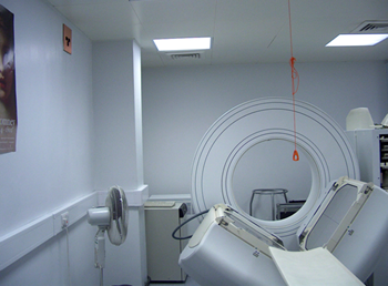
- Practical Setup
- Aquisition parameters
- Processing and Analysis
Move your mouse over the images to see a larger version.
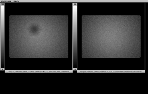
A point source is used to create a uniform flux of photons across the camera face. The resulting image should have a uniform count density. Major defects can be seen instantly (such as faulty PMTs or cracked crystal). Subtler effects can be recorded and monitored over time using standard uniformity results. These are dependant on the software used to perform the analysis but will generally include the standard NEMA results.
The obvious defect in the left image is due to a problem with the ADC connected to one of the photo multiplier tubes.
The NEMA standard for uniformity measurement uses the following conditions and definitions:
- The values are to be quoted for a matrix size that produces pixel sizes of 6.4mm ±30%. (ie.4.48 to 8.32mm)
- A minimum of 10,000 counts shall be collected in the centre pixel of the image.
- These two factors will normally mean a 64x64 matrix with 30million counts.
- The count rate shall not exceed 20,000 cps in the 20% energy window.
- The flood field image, after removing the edge pixels, shall be smoothed once by convolution with a 9-point filter function using the following weightings.
1 2 1 2 4 2 1 2 1 - The smoothed value shall be normalised by dividing by the sum of the weighting factors.
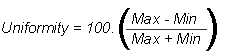
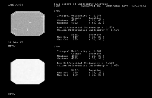
- Integral uniformity: The difference between the maximum and minimum pixel values across the UFOV and CFOV, as a percentage of the sum of these two pixels, ie.
- Differential uniformity: Is defined using the same equation as the integral uniformity, but the maximum and minimum pixel values are only from groups of five contiguous pixels. The calculation is performed on the rows and columns separately.
- These values are calculated over two areas, the useful field of view (UFOV) and the central field of view (CFOV). The central field of view is defined as being 75% of the UFOV.
Move your mouse over the images to see a larger version.