Gamma Cameras
Distortion corrections
- Introduction
- Spatial distortion / Linearity
- Energy Correction
- Uniformity correction maps
There are two basic types of gamma camera, digital and analogue. The analogue camera uses the basic positioning principles as the original Anger Gamma camera. This uses weighted voltages across the camera face to produce a x-y position and the sum of the PMT outputs proportional to the energy. This image output can then be corrected for the various distortions using lookup tables.
For digital cameras the signal from each PMT is measured and translated into a digital signal using Analogue to Digital Converters (ADCs). These signals can then be processed to produce the position and energy of the incident gamma ray. The distortion corrections can then be applied to either the individual ADC output or the resulting image.
Each manufacturer will use a slightly different method of correcting the raw image produced by the camera.
A number of corrections need to be applied to correct for the distortions inherent in the imaging system. These are:
- Spatial distortion or Linearity correction
- Energy correction
- Uniformity correction
- Count rate distortions – pulse pile up
Energy corrections account for the fact that the PMT will produce a higher signal (and hence higher measured energy) if the scintillation event is positioned near the centre of the PMT. This is a complex interaction, as it will tend to include more scattered photons in the centre of the PMTs and less of the true (unscattered) photons in areas towards the edge of the PMTs.
The uniformity correction map is the last correction to be applied to an acquired image and allows for slight variations in the sensitivity across the camera face. These should be described further in another part of this course. The correction map is normally acquired in a similar way to the intrinsic uniformity checks described here, but will include much higher count densities of one or two hundred million counts per detector.
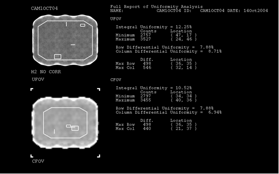
This flood image was acquired with non of the distortion corrections turned on.
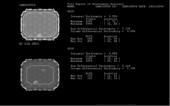
This flood image was acquired with only linearity correction turned on.
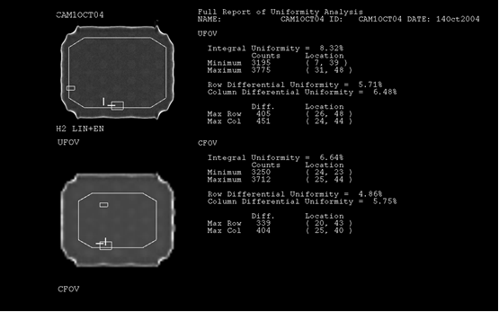
This flood image was acquired with only linearity and energy corrections turned on.
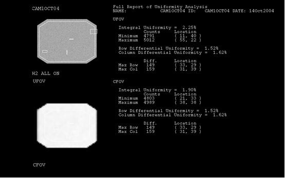
This flood image was acquired with all the normal corrections applied.