Gamma Cameras
Centre of Rotation COR
Move your mouse over the images to see a larger version.
The centre of rotation test measures the difference between the mechanical and electrical centres of rotation. Problems with the alignment will cause defects in the reconstructed images.
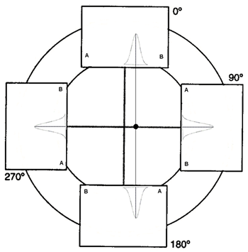
Most manufactures have their own way of measuring the COR. These will normally involve between one and five point sources positioned slightly offset from the mechanical COR.
A SPECT acquisition is acquired over 360 degrees for both heads (as opposed to a 180-degree acquisition for each head producing a total of 360 degrees).
The raw data when viewed as a dynamic image, will show the point source(s) moving from side to side sinusoidally. The projection data is not normally reconstructed.
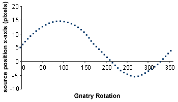
The position of the point source is ascertained using either the highest pixel value or some form of weighted position calculation. For the perfect system, the source position, when plotted against gantry rotation will map a straight line for the y-direction and a sine wave for the x direction.
The results for the x-axis are produced by calculating the deviation from a perfect sine wave. The y-axis results are produced by calculating the deviation from a straight line in the y-direction. For multi-detector cameras the average y position must also be compared.
Typical specifications for this test when using a 128x128 matrix are:
Mean x-axis offset <±0.4 pixels
Error range in x-axis < 1.0 pixels